CNC milling is one of the most efficient ways to turn a CAD design into a precise, functional part. The process uses computer-controlled rotary cutters to remove material and create features with tight tolerances — often down to ±0.01 mm. It works for metals, plastics, and complex geometries, making it a go-to method for prototypes and production runs.
In this guide, you’ll see what CNC milling is, how it works step by step, which machine types and materials you can choose, and the key design tips that can save cost and lead time.

What Is CNC Milling
CNC milling is a subtractive manufacturing process where a cutting tool removes material from a solid block — metal or plastic — to create your part. “CNC” stands for Computer Numerical Control, which means the entire process is guided by a digital program. The machine reads your CAD file, generates a toolpath, and executes every move with precision.
Compared to manual milling, CNC milling is faster, more repeatable, and capable of holding tight tolerances on complex parts. You don’t rely on an operator’s hand feel — the machine follows exact coordinates, which reduces human error and keeps every part consistent.
It’s also different from CNC turning: in milling, the tool rotates and the workpiece stays fixed (or moves slightly on a table), while in turning, the workpiece spins and the tool stays mostly stationary. Milling is the go-to choice for parts with prismatic shapes, pockets, slots, and complex 3D surfaces.
How CNC Milling Works – The Process Explained
It all starts with a CAD design — that’s your blueprint. The cleaner and more detailed your model is, the smoother the rest of the process will go.
From there, the design moves into CAM software. This is where toolpaths are generated and cutting strategies are decided. Feeds, speeds, and step-overs are not random guesses; they’re carefully calculated so the cutter removes material efficiently without damaging the part.
The CAM system then outputs G-code, which is basically the machine’s playbook. Every movement, every cut depth, every tool change is encoded so the mill knows exactly what to do.
Before the first cut happens, the machinist locks down the raw material using vises, clamps, or custom fixtures. If the workpiece isn’t secured properly, you risk losing accuracy or even damaging the part — so fixturing is a critical step.
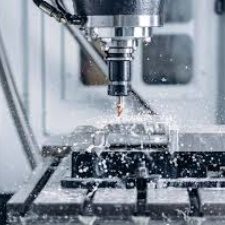
Then the real action begins. The machine faces the stock to create a reference surface, clears pockets, mills slots, drills and taps holes, and if needed, rotates or tilts to hit multiple sides in a single setup. This is where 3-, 4-, or 5-axis capability makes a huge difference for complex parts.
Once cutting is complete, quality control takes over. Parts are measured — often on a CMM — to confirm they meet spec. Any sharp edges are deburred, and surface treatments like bead blasting or anodizing are applied if required. The end result is a part that’s ready to use, not just a raw block of machined metal.
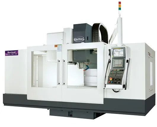
Types of CNC Milling Machines
The type of machine you choose has a big impact on what your part will cost and how fast it can be made.
3-Axis Milling – The Workhorse for Most Parts
A 3-axis machine moves the cutter along X, Y, and Z. It’s perfect for flat faces, simple pockets, and slots. If your part only needs machining from one side or two opposite faces, this is usually the most cost-effective choice. You avoid paying for capabilities you don’t need and get faster lead times.
4-Axis Milling – When You Need Multi-Side Features
The fourth axis lets the table rotate, which means the machine can cut features on multiple sides without stopping for re-clamping. This not only saves setup time but also improves accuracy because the part stays referenced in the same position. Use 4-axis when you have holes, cutouts, or pockets on adjacent faces — it will reduce human error and shorten your production schedule.
5-Axis Milling – For Complex Geometry and Tight Tolerances
A 5-axis mill adds simultaneous tilt and rotation, giving the tool access to nearly any angle. It’s the right call for organic curves, undercuts, or high-precision aerospace and medical components. While the hourly rate is higher, you often save money overall because the part is finished in one setup with fewer secondary operations and tighter tolerances.
| Machine Type | Typical Complexity | Cost Impact | Lead Time Impact |
| 3-Axis | Flat faces, basic pockets, slots | Lowest cost, ideal for simple parts | Fastest — minimal setup |
| 4-Axis | Features on multiple sides, angled holes | Moderate — fewer setups offset higher hourly rate | Faster than 3-axis with manual re-clamps |
| 5-Axis | Complex curves, undercuts, multi-face precision | Highest hourly rate but often cheaper overall | Shortest for complex parts — single-setup machining |
Match the machine to your design. Over-specifying can drive up cost, while under-specifying can hurt quality or delay delivery. If you’re not sure which machine your part needs, send us your CAD file — we’ll review it and suggest the most efficient setup.
Materials Used in CNC Milling

Choosing the right material isn’t just about availability — it directly affects cost, machining time, and part performance. Here’s a quick comparison to help you weigh your options:
| Material | Machinability | Key Advantages | Typical Applications |
| Aluminum (6061, 7075) | Excellent — fast cutting speeds, good surface finish | Lightweight, corrosion-resistant, affordable | Aerospace brackets, automotive housings, prototypes |
| Stainless Steel (304, 316L) | Moderate — slower cutting, requires coolant | Strength, heat resistance, hygienic surface | Medical instruments, food-processing equipment, marine parts |
| Mild & Tool Steel | Moderate to hard | High wear resistance, durable | Gears, shafts, mold bases, tooling components |
| Copper & Brass | Good — easy to machine | Excellent conductivity, aesthetic finish | Electrical contacts, heat sinks, decorative parts |
| Titanium | Difficult — requires rigid setups | Exceptional strength-to-weight ratio, biocompatible | Aerospace structural parts, medical implants |
| POM (Delrin®) | Very easy — produces clean chips | Low friction, dimensionally stable | Bushings, gears, mechanical components |
| Nylon (PA6, PA66) | Easy but moisture-sensitive | Tough, impact-resistant | Bearings, fixtures, consumer product housings |
| PEEK | Harder to machine but stable | High temperature and chemical resistance | Aerospace, semiconductor, medical components |
| ABS / PC | Easy | Cost-effective, impact resistant | Prototypes, enclosures, low-volume parts |
Selecting the right material early can save you time and money. For example, switching from stainless steel to aluminum for a non-critical bracket can cut machining time in half, which means lower cost and faster delivery. If you’re unsure what’s best for your design, send us your CAD file — we can suggest materials that balance strength, weight, and budget.
Surface Finishes for CNC Milled Parts
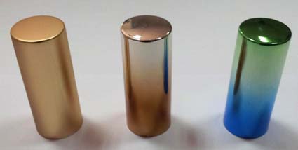
CNC milling already produces parts with a smooth, functional surface. As-milled finishes typically have a roughness average (Ra) of 3.2 μm or better, which is suitable for most mechanical applications.
If your part is customer-facing or needs additional protection, post-processing can take it further:
| Surface Finish | What It Does | Best Use Case |
| Bead Blasting | Creates a uniform matte texture and hides tool marks | Ideal for cosmetic parts where appearance matters |
| Anodizing (Type II / III) | Adds corrosion resistance and color options; Type III creates a hard, wear-resistant layer | Aerospace, consumer electronics, outdoor applications |
| Powder Coating | Applies a tough, decorative coating available in many colors | Enclosures, handles, and parts exposed to wear or chemicals |
| Polishing & Buffing | Produces a mirror-like reflective surface | High-end consumer products, optical components |
| Laser Engraving | Permanently marks part numbers, barcodes, or logos | Traceability, branding, or regulatory compliance |
Choosing the right finish is about balancing function, aesthetics, and cost. We can recommend the best option for your application so you get a part that looks and performs exactly as you expect.
CNC Milling Tolerances
When you design a part, you want to know exactly how close the final result will be to your CAD model. CNC milling is known for its ability to hold tight tolerances. On most projects, ±0.01 mm (±0.0004 in) is achievable on critical features, provided the material and part geometry allow it.
It’s important to note that not every feature needs the tightest possible tolerance. Over-specifying can drive up machining time and cost because it requires slower feeds, more tool passes, and extra inspection. A smart approach is to apply tight tolerances only where they truly matter — such as mating surfaces, critical holes, or sealing faces — and leave other areas with looser general tolerances.
Several factors can affect achievable tolerances, including material hardness, part size, tool deflection, and thermal expansion during cutting. If your design has challenging features, it’s worth sharing your CAD model early so we can review it and confirm what’s realistic before production begins.
Advantages & Limitations of CNC Milling
Advantages of CNC Milling
- High Precision and Repeatability: CNC milling delivers parts with tolerances down to ±0.01 mm, making it ideal for assemblies where every component must fit perfectly. Because the process is computer-controlled, the first part and the thousandth part come out exactly the same — a critical benefit for production runs.
- Broad Material Flexibility: You can mill a wide variety of materials without changing processes. Aluminum is great for lightweight brackets, stainless steel offers strength and corrosion resistance, and plastics like POM and PEEK are perfect for functional prototypes. This flexibility makes it easy to compare designs across materials.
- Scalable for Prototypes and Production: CNC milling is equally effective for a single prototype or a full production run. You can validate your design quickly and then scale up without switching to a new manufacturing method.
- Good Surface Quality: As-milled surfaces are often smooth enough for functional use. When appearance or special performance is important, you can add bead blasting, anodizing, polishing, or coating to achieve the finish you want.
Limitations of CNC Milling
Complex designs with deep cavities, thin walls, or undercuts require special tooling and multiple setups. This increases machine time and labor. Because milling removes material, there’s also more waste — a factor when machining expensive alloys like titanium. And if you only need one part but the setup is elaborate, that setup time alone can make the part costly.
Design Tip
Keep your part design as simple as possible for the function it serves. Reducing unnecessary complexity saves both time and money. If you’re unsure, send us your CAD model — we can review it and suggest cost-saving adjustments before production.
Design Guidelines for CNC Milled Parts

Good design decisions can make your parts easier — and cheaper — to machine. Following these guidelines helps reduce cycle time, improve tool life, and avoid costly rework.
| Design Feature | Recommended Guideline | Why It Matters |
| Minimum Wall Thickness | ≥ 0.8 mm for metals, ≥ 1.5 mm for plastics | Thicker walls reduce vibration and prevent warping during machining. |
| Internal Corner Radius | Use radii ≥ 1/3 of cavity depth | Sharp corners require small tools and slow passes; adding radii speeds up cutting and lowers cost. |
| Hole Diameters | Design holes ≥ 1 mm and in standard drill sizes | Non-standard diameters require end milling instead of drilling, increasing machining time. |
| Pocket Depth | Keep depth ≤ 4× pocket width for best results | Deep pockets cause tool deflection and poor finish; shallower pockets allow faster, more accurate milling. |
| Chamfers and Fillets | Add 0.5–1 mm chamfers or fillets where possible | Breaks sharp edges, improves part safety and appearance, and reduces deburring time. |
| Tolerances | Apply tight tolerances only where needed | Overly tight tolerances increase cost due to slower feeds, extra tool passes, and additional inspection. |
| Fixturing Considerations | Design with flat surfaces for secure clamping | Better fixturing means more accurate parts and fewer setup changes. |
By considering these points early, you avoid common pitfalls like chatter, tool breakage, or excessive cycle time. We can review your CAD files and suggest changes that save machining hours and keep your project on budget.
Common Applications of CNC Milling
CNC milling shows up in almost every industry — but the way you use it may depend on where you are in the product lifecycle. Here are the most common ways engineers and manufacturers put it to work:
Rapid Prototyping and Design Validation
When you need to turn a CAD file into a physical part quickly, CNC milling is one of the most reliable options for rapid prototyping. It lets you check form, fit, and function on a real component before committing to expensive tooling. Many of our clients iterate through several prototypes this way, catching design issues early and avoiding costly rework later.
Production of End-Use Parts

Milling isn’t just for prototypes — it’s a go-to process for low- and medium-volume production. Aerospace brackets, automotive housings, and medical device components are often CNC-milled because the process delivers the precision and repeatability those industries demand. If you need consistent quality across hundreds or thousands of parts, milling is a safe choice.
Tooling, Jigs, and Fixtures
CNC milling also supports your manufacturing process itself. Custom jigs and fixtures, mold inserts, and inspection gauges can all be milled with high accuracy. Well-designed tooling can reduce assembly time, improve operator safety, and maintain consistent part quality on your production line.
Cost Factors in CNC Milling
Understanding what drives CNC milling costs helps you make smarter design and sourcing decisions. Here’s what matters most — and how you can keep costs under control.
- Material Choice: The material you pick affects both raw material cost and machining time. Aluminum is fast to cut and affordable, while stainless steel and titanium take longer to machine and wear tools faster. If strength isn’t critical, switching from stainless to aluminum can cut costs dramatically.
- Part Geometry and Complexity: Deep pockets, thin walls, and undercuts require slower feeds, smaller tools, or multiple setups — all of which add machine time. Simplifying features, adding internal radii, or reducing pocket depth can save hours of cutting time and lower your bill.
- Quantity and Setup Time: Setup is a fixed cost: programming, fixturing, and first-article inspection happen whether you make one part or a hundred. Spreading setup cost over a larger batch usually reduces the per-part price.
- Tolerance Requirements: Tighter tolerances mean slower feeds, more passes, and extra inspection. Only call out ±0.01 mm where it really matters — leaving standard tolerances on non-critical surfaces can save you time and money without hurting performance.
- Secondary Operations and Finishing: Anodizing, powder coating, or polishing can add value but also add cost and lead time. Plan early which surfaces actually need finishing so you don’t pay for unnecessary work.
Cost-Saving Tip: Send your CAD file for a quick DFM review before production. We can point out features that drive up cost — and suggest small design changes that shorten cycle time and reduce price.
Future Trends in CNC Milling
CNC milling isn’t standing still — it’s getting faster, smarter, and more connected. Understanding where the technology is heading helps you plan for future projects and stay competitive.
- Smarter Automation: Automatic workholding systems are becoming more common, allowing machines to swap parts without operator intervention. This means lights-out machining — running parts overnight — which can shorten lead times and lower labor costs.
- Real-Time Tool Monitoring: Modern CNC mills are being equipped with sensors that track tool wear, vibration, and cutting forces. This allows predictive maintenance and helps avoid unexpected tool breakage that can scrap a part or stop production.
- AI-Driven Toolpath Optimization: CAM software is starting to use AI to generate more efficient toolpaths. The result is shorter cycle times, less tool wear, and improved surface finish — all without the programmer spending hours tweaking parameters manually.
- Fully Connected Digital Shops: Industry 4.0 is connecting machines, inspection equipment, and ERP systems. This allows real-time tracking of part status, better scheduling, and faster response when changes are needed. For you, this means more transparency and fewer surprises in project timelines.
Conclusion
CNC milling remains one of the most dependable ways to turn your design into reality — combining precision, repeatability, and material flexibility in a single process. Whether you need one prototype to validate a concept or a full production run with tight tolerances, milling gives you the accuracy and consistency to trust your results.
If you want to save time, reduce cost, and avoid design surprises, let us take a look at your CAD file. Our team will review it, suggest any optimizations, and provide a fast, accurate quote so you can move forward with confidence.
FAQs about CNC Milling
What tolerances can CNC milling achieve?
For most projects, CNC milling can hold tolerances as tight as ±0.01 mm (±0.0004 in) on critical features, depending on material, geometry, and machine stability. This level of precision is more than enough for most assemblies and mating components.
It’s important to avoid over-specifying tolerances. Applying ultra-tight tolerances to every feature can drive up machining time, require slower cutting speeds, and add extra inspection steps — all of which increase cost. A good approach is to use tight tolerances only where they matter, such as for mating holes, sealing faces, or precision slots, and keep standard tolerances for non-critical features.
If your part has unique requirements, share your CAD model with us. We can review your design, confirm what tolerances are achievable, and suggest adjustments to balance precision and cost.
How fast can CNC-milled parts be delivered?
Prototype CNC milled parts can ship in as little as 2–3 business days after order confirmation. Low-volume production typically takes 5–7 business days, and larger production runs are scheduled based on quantity and complexity.
If you have a tight deadline, expedited services are available. Let us know your required delivery date when requesting a quote, and we’ll prioritize your job to keep your project on track.
Can CNC milling produce prototypes and production parts?
Yes — CNC milling is one of the most versatile processes for both rapid prototyping and low-to-medium volume production. You can start with a single part to check form, fit, and function, then scale up to hundreds or thousands of parts without changing the process.
Because the same digital program is used for every run, your first part and your last part will match, which is critical for assemblies that require consistent dimensions. If you plan to move from prototyping to production, we can help you optimize your design early so you avoid expensive rework later.
What file formats do you accept for quoting?
We accept the most common 3D CAD file formats, including STEP (.step, .stp), IGES (.igs, .iges), and Parasolid (.x_t, .x_b) for accurate machining data. STL files are also supported for prototypes, and you can attach 2D drawings (PDF, DXF) if you need to specify dimensions or tolerances clearly.
All files are handled under strict confidentiality, and we can sign an NDA upon request to protect your intellectual property.
How do I reduce CNC milling costs?
The biggest cost drivers in CNC milling are part complexity, setup time, and material choice. Here are a few proven ways to keep costs under control:
- Simplify Geometry: Avoid unnecessarily deep pockets, sharp internal corners, and very thin walls. Adding corner radii and keeping pocket depth reasonable reduces tool changes and machine time.
- Apply Tolerances Wisely: Use tight tolerances only where they are functionally critical. Over-specifying tolerances increases cutting time and inspection cost.
- Choose Materials Carefully: Switch to aluminum or engineering plastics if strength and temperature resistance are not critical — they machine faster and cost less.
- Batch Production: Order slightly higher quantities when possible to spread setup cost across more parts and reduce the per-part price.
- Plan Finishes Early: Specify only the necessary surfaces for anodizing, bead blasting, or polishing to avoid paying for unnecessary post-processing.
A quick DFM review before production can highlight these opportunities. Share your CAD model with us, and we can suggest design tweaks that cut cycle time and save money without sacrificing performance.
